Introduction
Here's the thing, I love fresh herbs for my salads, but have a tendency to forget to water them properly... In the summer I keep my little garden on my balcony and it does pretty well, but in the winter it must be kept indoors.With the winter and it's shorter days coming, two T5 tubes of 28W each were installed to help these little plants. There were happy and thriving:
 |
| Original setup with a regular timer |
I also wanted to water them automatically, and play with a raspberry pi this rainy weekend, so I started to gather ideas:
Project specifications
The system must:
- Be autonomous for two weeks (I will leave for two weeks in France for vacations soon)
- Be quite simple and not cumbersome, I do not want a heck of a network and cables running in my kitchen
- Be able to oxygenate the fertilizer solution to provide dissolved oxygen to the roots of the plants
- Run on a PI for the fun of it
- The the system will run on a gallon of water + fertilizer mix controlled by a valve
Oxygenating the solution is important: Oxygen helps the roots to absorbs nutrients, it also helps stirring the solution before pouring it on the soil.
- The the system will run on a gallon of water + fertilizer mix controlled by a valve
Oxygenating the solution is important: Oxygen helps the roots to absorbs nutrients, it also helps stirring the solution before pouring it on the soil.
Hardware
Here is the list of the necessary hardware:
- RaspberryPi Rev2 board + SD card
- A samsung smartphone charger for the power supply
- A samsung smartphone charger for the power supply
- Relay module
- Valve gravity feed 110V
- Small wiring for the board, scavenged from phone lines cables
- 110V electrical cord for the light, valve, air pump
- Transparent aquarium airline tubing + T-splitters
- Black aquarium airline tubing + T-splitters
- Aquarium air pump
- Screws, glue, tape
I used the black airline tubing for the water+fertilizer solution from the tank to the plants. This is important as we do not want any sunlight going throw the solution and algae growing in the tubes and valve... The 1 gallon tank also need to be black or stored in the dark.
I used the black airline tubing for the water+fertilizer solution from the tank to the plants. This is important as we do not want any sunlight going throw the solution and algae growing in the tubes and valve... The 1 gallon tank also need to be black or stored in the dark.
Building the system
Raspberrypi and relay module
By looking at the I/O availables for the pi, I selected 3 I/Os that will be used as outputs to control the relays and soldered a cable to connect the two boards.
The selected IO as 14, 15 & 18 on the P2 connector. The same connector provides +5V and GND to power the relay board. Each relay does not consumed much and the PI power supply can take that load. Moreover all relays on the board are driven by optocouplers, this is nice as each GPIO cannot provide enough current to directly drive a relay.
In order to make the link between these boards I used a 14 pins IC socket that was cutted in two and solder the wires on the two half sockets. That way the board can easily be connected and disconnected.
After booting up the pi you can configure the setup of the OS and install a few things. I would recommend these importants steps to configure:
- Maximize the partition to the size of the SD card (gives more room than the original image)
- Enable SSH server (allows to remotely connect to the pi)
- Change password (123456789)
- Reduce the memory shared by the GPU to 16MB (we'll not need the GPU for displaying graphics)
I also installed Apache/MySQL/PHP in order to maybe provide an webinterface to the watering system but haven't found time to code that yet.
The idea then was to use crontab to start scripts that will energize the relays for taking care of my herbs
- One for controlling the light
- One for controlling the air pump
- One for controlling the watering valve
All scripts will be controlled by one configuration file
Each of the scripts will write in a logfile what is beeing executed and at what time.
The scheduling will be done by crontab, that will run one or the other scripts at defined time.
I wanted to avoid a water disaster, but haven't worked on monitoring the system, I would need to read the power given to the valve. However at worst I have a gallon of water in my kitchen which is no so bad :)
Basically all files starts with: importing libraries, starting a log file, reading the configuration file and initializing the GPIO of the PI. The following code is the beginning of the lightSTART.py file
Others are linked within the page
The selected IO as 14, 15 & 18 on the P2 connector. The same connector provides +5V and GND to power the relay board. Each relay does not consumed much and the PI power supply can take that load. Moreover all relays on the board are driven by optocouplers, this is nice as each GPIO cannot provide enough current to directly drive a relay.
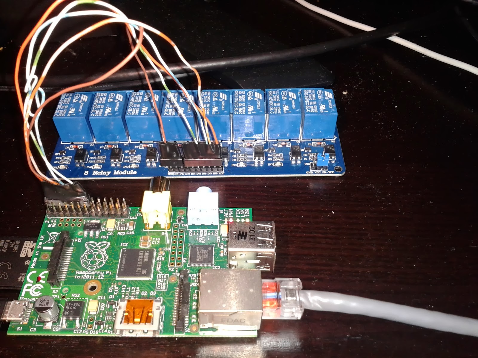 |
| Wired pi and relay module |
 |
| Splitted in two, this offers a nice and cheap connector. |
Setting up the PI
The first step is to download the Raspbian OS and put it on a SD card. This step takes some time but is quite easy buy following the steps on the elinux beginner guide.After booting up the pi you can configure the setup of the OS and install a few things. I would recommend these importants steps to configure:
- Maximize the partition to the size of the SD card (gives more room than the original image)
- Enable SSH server (allows to remotely connect to the pi)
- Change password (123456789)
- Reduce the memory shared by the GPU to 16MB (we'll not need the GPU for displaying graphics)
I also installed Apache/MySQL/PHP in order to maybe provide an webinterface to the watering system but haven't found time to code that yet.
The idea then was to use crontab to start scripts that will energize the relays for taking care of my herbs
Scripting
The best way I found to command the GPIO for a PI is a python library called RPi.GPIO. I have very little experience in Python but prefer it than bash scripts ;) This library is very simple to use.Scripts specifications
The project will be made of 3 scripts:- One for controlling the light
- One for controlling the air pump
- One for controlling the watering valve
All scripts will be controlled by one configuration file
Each of the scripts will write in a logfile what is beeing executed and at what time.
The scheduling will be done by crontab, that will run one or the other scripts at defined time.
I wanted to avoid a water disaster, but haven't worked on monitoring the system, I would need to read the power given to the valve. However at worst I have a gallon of water in my kitchen which is no so bad :)
Scripts themselves
Here is the code for each of the python scripts, all the files can be found on this github repo.Basically all files starts with: importing libraries, starting a log file, reading the configuration file and initializing the GPIO of the PI. The following code is the beginning of the lightSTART.py file
import RPi.GPIO as GPIO, time, logging, sys, signal, ConfigParser, os
#setup logging class
dir = os.path.dirname(os.path.abspath(__file__))
logfile = dir + '/logs/info.log'
logging.basicConfig(filename=logfile, level=logging.INFO)
#read configuration file and retrieve light duration
Config = ConfigParser.ConfigParser()
Config.read(dir + '/config.ini')
duration = Config.getint('params','light')
#configure GPIO
GPIO.setwarnings(False)
GPIO.setmode(GPIO.BCM)
LIGHT = 14
GPIO.setup(LIGHT, GPIO.OUT, initial=GPIO.HIGH)
The rest of the code will handle signals that can be sent to the process in case of Ctrl+C is pressed to halt the script, and the start() method that starts the light itself.
def signal_handler(signal, frame):
        msg = 'You pressed Ctrl+C! Lighting STOPPED'
        logging.info(time.asctime(time.localtime()) + ' ' + msg)
        print msg
        GPIO.output(LIGHT, GPIO.HIGH)
        sys.exit(0)
signal.signal(signal.SIGINT, signal_handler)

def start():
        #starting the light and saving the time at which it started
        start = time.time()
        GPIO.output(LIGHT, GPIO.LOW)
        msg = 'Light STARTED'
        logging.info(time.asctime(time.localtime(start)) + ' ' + msg)
        print msg

        #checking how much time has elapsed every hours
        #if time elapsed is more than 8 hours then break
        elapsed = 0
        while True:
                elapsed = (time.time() - start)
                if elapsed > duration:
                        break;
                time.sleep(1)

        #shutting the light down after 8 hours
        GPIO.output(LIGHT, GPIO.HIGH)
        msg = 'Light STOPPED after %d seconds' % elapsed
        logging.info(time.asctime(time.localtime(start)) + ' ' + msg)
        print msg


if __name__ == "__main__":
        start()
I chose to use methods instead of creating a flat script so I can load this as a module in other scripts if needed and call the start() method. Basically all scripts are using the same structure, with different GPIO configuration and timings.
I do not really like the while loop running for 8 hours... In that case I'd maybe better do something like a crontab task to start the light and one to stop the light. Or maybe I could do a script called every minute to check what is the current time and decide if the light should be ON or OFF, that way if the power fails and the system reboots, the light will be ON.
My PI is not connected to the network in "regular operation". I use a long cable across my appartment for debugging only. This makes the project fragile against power outages as the clock will be lagged (as long as the outage lasts) for the execution of the crontab. By default Raspbian has no RTC chip, so it tries to :
- get the time from NTP server at boot and every 3 hours
- get the time from the fake-hwclock module
- set the time to the fake-hwclock every hour
As the Pi will not have NTP option available, a crontab job is defined to set the fake-hwclock every minute instead of every hour. That way in the case of a power failure the system clock will be delayed only by as much time as the power outage lasts. And not by increments of one hour.
Crontab jobs
There are three crontab jobs, edit them using >sudo crontab -e.
The RPi.GPIO python library needs root access to change the state of the I/Os, moreover the root level is required to set the clock to fake-hwclock, so sudo is necessary.
The RPi.GPIO python library needs root access to change the state of the I/Os, moreover the root level is required to set the clock to fake-hwclock, so sudo is necessary.
* * * * * fake-hwclock save
0 6 * * * /home/pi/scripts/lightSTART.py 2>>/home/pi/scripts/logs/cron.log
0 11 * * * /home/pi/scripts/airWaterSTART.py 2>>/home/pi/scripts/logs/cron.log
Redirecting the STDERR output to a file helped me a lot debugging the execution of the scripts, now it could be taken away but I keep this configuration for a while to see how the system runs. It could still be considered a testing phase as the system is less than 24 hours old now.
Installation
For the setup I wanted minimal impact on my kitchen environment so I tried to hide everything in and under the cabinets. In the cabinets I put a 1 gallon water bottle that contains the fertilizer solution and the air pump. The water line and electricity for the pump are running though a small hole at the bottom of the cabinet:
 |
| Gallon filled up with clear water in the cabinet. Air pump in the front. Air and water lines coming from the top of the jar. Lots of flour for making lots of crepes ! |
The electronics is secured upside down under the same cabinet, and wires are organized to have a minimal impact on my view :) What I can see when I'm standing up there are only the line for the water/fertilizer and the electrical cord for the valve and the light.
The valve gave me some trouble... a few leaks. I used two bronze threaded adapted from 1/16 inch pipe to 1/4 inch pipe. The transparent 1/4 inch pipes are connected to the solenoid gravity feed valve. There were taped black later on to avoid light and algae growing in the pipes and valve.
The valve outlets were polished off, because by default there was an imperfection that let air and water leak. It's probably due to the fact that the valve was made of two plastic pieces melted together and it left and edge.
 |
| Power strip tapped in from behind the microwave Relay board (blueish) and Pi module temporarily connected to the network The circular object on the front is a kitchen workplan light |
 |
| This setup was good but leaked around the valve and adapters. The bronze adapters were leaking though the threading, so there were filled with super glue The valve was leaking due to plastic molding imperfections that were polished off |
 |
| The little linear edge can be seen on the top of the outlet. This was sanded off. |
Watering the plant themselves was done using the black pipe fastened using cable ties on kebab sticks:
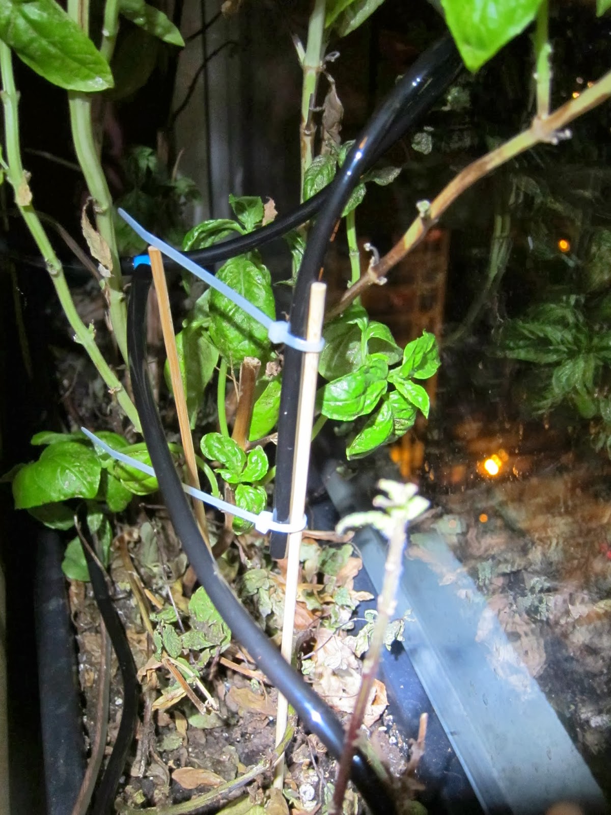 |
| Black pipes are bringing the fertilizer solution to the plants. |
Update:
The pipes that bring the solution to the plants deliver very inequal amounts of solution, some where not outputing anything...
In order to solve that issue I decided to raise the pressure in the tubes, that way a little difference of output height will not make a big difference to the flows. So the plan was to seal the output, and leave only a tiny opening. This tiny opening will make the pressure raise in the tube and level out the amount of solution delivered per output.
Well it was late in the evening and I wanted to fix that, so how to seal the output and only leave a tiny opening:
 |
| Yep, a screw at each output: Regulates the flow as the solution can only go though the threading to get out of the tube |
Voilà!
It was a fun Sunday, I havent done such DIY things since a long time and remembers me my old time.
I'll need to adjust the watering time, any maybe will post a picture when the plants thriving again!
I'll need to adjust the watering time, any maybe will post a picture when the plants thriving again!
References
Syntax Highlighting with Blogger Engine: http://www.craftyfella.com/2010/01/syntax-highlighting-with-blogger-engine.htmlOthers are linked within the page